-
tel: +86 21 5299 9232
-
email: inquiry@rsid-solutions.com

EN

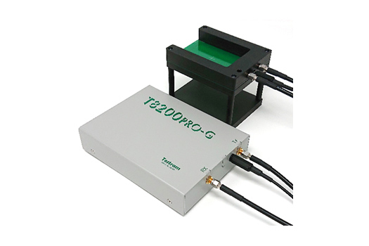
T8200PRO-G is a top RFID comprehensive tester from Testram Japan. It’s a good choice for RFID, Smart card (contactless and dual interface), the development and manufacturing of power inductors, scientific research and education, laboratories or testing institutions and easily integrate into an automated production line.
Key Features
• Accurately measure the parameters of various sizes of LF & HF devices of various sizes, include:
Resonant frequency, attenuation, Q value, support to read UID code and recognize some chips.
• Able to test transmission or reflection properties (Including directional coupling), Adjustable RF input power, Analog card reader.
• Test results and waveform can be automatically written to the log file.
• Preset testing range to determine whether the sample is qualified.
• Single computer version (for single use) and on-line automation solutions (for mass production).
Applications
• Smart card, RFID tag resonance frequency detection:
Tell the measurement result is correct or not; automatically generate check log files;
Adjustable RF power -30dBm~15dBm.
RF antenna can be detected before chip binding, such as dual interface card coil inlay.
• RFID read/write antenna resonant frequency detection.
• Self-resonance frequency detection of wireless power supply coil and power inductor.
Test Results

Specifications
|
Testing Principle |
• Contactless resonance frequency with magnetic coupling |
|
Measuring Mode |
• Transmission/reflection characteristics |
|
Protocol |
• ISO14443A (MIFARE Classic, MIFARE Ultralight) |
|
Data Points |
• 100~2048 points |
|
Test Time (data points=1000) |
• Without ID reading: 0.5 sec (typ) • With ID reading: 1 sec (typ) |
|
Log File |
• Log file (csv): • UID, PASS/FAIL, Resonance Frequency, Attenuation, Q Value |
|
Frequency Range |
• 10KHz~100MHz |
|
Application Power (50Ω load) |
• -30~15dBm |
|
DIO Interface (optional) |
• Isolated input/output |
|
System Requirements |
• PC(OS) Windows7, Windows8.1, Windows10 • ≥USB2.0 |
|
Power Supply |
• USB bus power (current consumption≤500mA) |
|
Packaging List |
• Main unit, USB cable, Coaxial cable(500mm x2), High frequency standard card size test fixture, Optional different size specifications for testing antenna plates, Install CD |
|
Dimension Weight |
• 125(W)x165(D)x40(H)mm, Protrusion not included, 0.8kg |
• Accurately measure the parameters of various sizes of LF & HF devices of various sizes, include:
Resonant frequency, attenuation, Q value, support to read UID code and recognize some chips.
• Able to test transmission or reflection properties (Including directional coupling), Adjustable RF input power, Analog card reader.
• Test results and waveform can be automatically written to the log file.
• Preset testing range to determine whether the sample is qualified.
• Single computer version (for single use) and on-line automation solutions (for mass production).
| Testing Principle | • Contactless resonance frequency with magnetic coupling |
| Measuring Mode | • Transmission/reflection characteristics |
| Protocol | • ISO14443A (MIFARE Classic, MIFARE Ultralight) • ISO14443B (Only PUPI), Felica • ISO15693 (Tag-it HF-I Plus/Pro, ICODE SLIX2) |
| Data Points | • 100~2048 points |
| Test Time (data points=1000) | • Without ID reading: 0.5 sec (typ) • With ID reading: 1 sec (typ) |
| Log File | • Log file (csv): • UID, PASS/FAIL, Resonance Frequency, Attenuation, Q Value • Waveform format: csv, jpg |
| Frequency Range | • 10KHz~100MHz |
| Application Power (50Ω load) | • -30~15dBm |
| DIO Interface (optional) | • Isolated input/output |
| System Requirements | • PC(OS) Windows7, Windows8.1, Windows10 • ≥USB2.0 |
| Power Supply | • USB bus power (current consumption≤500mA) |
| Packaging List | • Main unit, USB cable, Coaxial cable(500mm x2), High frequency standard card size test fixture, Optional different size specifications for testing antenna plates, Install CD |
| Dimension Weight | • 125(W)x165(D)x40(H)mm, Protrusion not included, 0.8kg |
NFC Tag Antenna Q Factor Definition and Impact
The Q factor (quality factor) is a key parameter for measuring the energy efficiency of an antenna resonant circuit. The calculation formula is Q = 2π × (stored energy / energy loss per cycle). For NFC tag antennas:
- High Q value (>30): The antenna resonance peak is sharp, energy is concentrated, and the communication distance is long, but the bandwidth is narrow (e.g., 13.56 MHz ±100 kHz). It is easily affected by minor frequency shifts or environmental interference.
- Low Q value (<15): The bandwidth is wider (e.g., ±500 kHz), with high fault tolerance but significant energy loss. The typical communication distance may be reduced from 10 cm to below 3 cm.
Core Design Parameters Affecting Q Factor
- Conductor Loss:
- Copper wire (resistivity 1.68×10⁻⁸ Ω·m) has a Q factor 36% higher than aluminum wire (2.65×10⁻⁸ Ω·m).
- Increasing the wire width from 0.1 mm to 0.3 mm reduces conductor resistance by approximately 67%, significantly improving the Q factor.
- Structural Optimization:
- A 4-turn square coil (inductance ≈1.2 μH) has a Q factor 40% higher than an 8-turn coil (inductance ≈3 μH), but it must be matched to the chip capacitance (typical range 50-200 pF).
- Reducing the coil spacing by 20% increases proximity effect losses, reducing the Q factor by approximately 15%.
- Substrate Material:
- FR4 (tanδ = 0.02) has 10 times higher dielectric loss than polyimide (tanδ = 0.002), reducing the Q factor by approximately 25%.
- Reducing the substrate thickness from 0.8 mm to 0.2 mm reduces parasitic capacitance by approximately 30%, improving resonance frequency stability.
- Impedance Matching:
- A mismatch between the chip input impedance (typically 1-10 kΩ capacitive) and the antenna impedance (typically 0.5-5 Ω inductive) exceeding 20% can result in energy reflection losses of over 30%.
Necessity of 100% Online Full Inspection of Q Factor
- Process Fluctuation Control:
- Etching wire width tolerance of ±0.02 mm can cause inductance variations of ±5%, leading to Q factor fluctuations of ±8%.
- A 10% change in lamination pressure can cause a dielectric constant shift of 3%, resulting in a resonance frequency shift of approximately 1.5 MHz.
- Cost-Benefit Analysis:
- NFC tags with undetected low Q values (<10) can result in a read failure rate of over 5% in logistics applications.
- Online testing systems (e.g., Keysight VNA solution) can complete testing in <300 ms per unit, improving yield by 3-5 percentage points compared to offline sampling.
- Reliability Verification:
- High and low-temperature cycling (-25°C to 85°C) tests show that tags with Q factor changes exceeding 15% have an 80% higher failure probability in extreme environments.
- In vibration tests, tags with poor Q factor stability have a threefold increase in mechanical failure risk.
Typical Case Data
Production data for an automotive key NFC tag:
- Batch pass rate improved from 92.7% to 99.3% after implementing full inspection.
- Defects detected by the online testing system:
- Coil breaks (0.8%)
- Impedance mismatch (0.5%)
- Material defects (0.4%)
- Poor soldering (0.3%)
This level of quality control increases the mean time between failures (MTBF) from 5 years to over 8 years, meeting the automotive-grade AEC-Q100 standard requirements.
Asia:

Europe:


North America:
South America:


Africa:
Oceania:
Special:


Services before Sales
- Reply your inquiry within 24 hours.
- Communication by email.
- Welcome you visiting our factory and final users in China.
- Help for VISA application and Invitation Letter issuing.
- We afford you consultation for 24 hours of 7 days in the process of sale and after service by phone or mail. We will support you for advisory opinion in purchasing, explanation in various technical problems and reliable supply in technique support.
Services on Purchasing
- Communication by email.
- Welcome you visiting our factory and final users in China.
- Help for VISA application and Invitation Letter issuing.
Services after Sales
- Online Support, 24 hours feedback once got the email
- Enough Spare Parts Preparation for you…
- Engineer to customer’s site for training & repairment
- Our equipments have 12 months for quality guarantee after sale. If the equipments do not work because of self cause, we will do free service and change the damaged spare parts.
- We will do life-long maintenance for all of our sold equipments. After quality guarantee period, if you can not maintain the equipments by self, we are under an obligation to go to work place and assist you to make maintenance. The cost of spare parts as well as expenses of traveling and man-hour of worker will be negotiated separately. Spare parts will be supported whether during guarantee period or not.
- After have finished maintenance, our service engineer will do training for the operators in plenty of time so that operators can be ensured to independently make operation, debugging and daily plant maintenance.
Commercial FAQ
Warranty of consumable product is be defined according to the difference of product properties, our sales representative will state it clearly before you purchase.
Related Products


CONTACT US
Contact US
Product Information
Quantity
Unit
Piece
Support order samples, customization, wholesale direct, and complete payment. If the product you look for does not have corresponding customized content, pls fill out the form below to contact us, and we will reply ASAP.